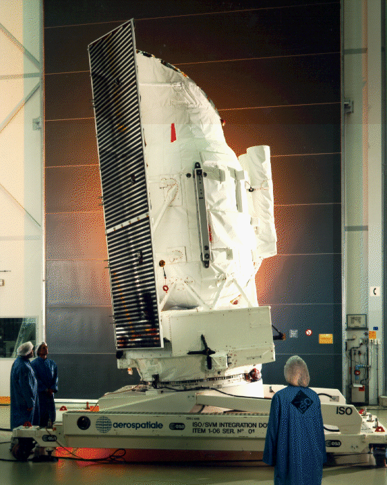
From late 1995 until April 1998, the Infrared Space Observatory ISO was gathering spectroscopic data in the infrared. One of the instruments, the Short Wavelength Spectrometer (SWS), was built by SRON (PI) in collaboration with MPE-Garching and KU-Leuven. The data obtained are available in the ESA archive.
The Short Wavelength Spectrometer (SWS)
The Short Wavelength Spectrometer (SWS) was one of the four instruments onboard of ESA’s Infrared Space Observatory ISO. It was designed for spectroscopic observations with medium and high resolution in the 2.38 – 45.2 µm and the 11.4 – 44.5 µm range, respectively. The observations are publicly available in the ESA archive.
The SWS wavelength range was of great scientific interest because cool objects with temperatures of 80-1500 K radiate the bulk of their energy in this range and because of its rich variety of atomic, ionic, molecular and solid-state spectral features. These provide unique and excellent tools for studies of the physical and chemical processes in the universe, especially of those regions optically hidden by interstellar dust. The SWS spectral resolution allowed probing of kinematic processes in a variety of objects ranging from nuclei of galaxies to planetary atmospheres. With the SWS sensitivity, line studies of extragalactic objects out to the distance of the Virgo cluster and beyond could be carried out. Direct observation of the ground state of H2 in the interstellar medium was possible.

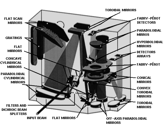
The SWS consisted of two nearly independent grating spectrometers, one for the short-wavelength range from 2.4 – 12 µm and one for the long-wavelength range from 12 – 45 µm. In the long-wavelength spectrometer, Fabry-Pérot filters could be inserted for which the grating worked as an order sorter. The SWS had 17 AOT bands (11 for the grating and 5 for the FP), 3 apertures, 6 detector arrays (4 arrays of 12 detectors for the grating and 2 arrays of 2 detectors for the FP) and the instrument covered 4 orders. The scanning of the wavelength was achieved through a rotating mirror which could scan the total range in discrete steps.
The SWS had three entrance apertures. The IR radiation was reflected into the SWS apertures by the ISO pyramidal mirror. The appropriate aperture was selected by specific pointing of the ISO satellite. The spacecraft had to be adjusted in a way that the target is imaged onto the selected aperture. A four-position shutter mechanism permited the opening of any one of the three apertures or blocking of all.
Each of the entrance apertures was used for two wavelength ranges. Dichroic beamsplitters behind the apertures split the incoming radiation in a short and a long wavelength part. The beams transmitted by the crystal entered the Short Wavelength (SW) section of the spectrometer. The reflected beams entered the Long Wavelength (LW) section, after a second reflection against identical material. Since the two sections were otherwise independent, the two wavelength ranges could be observed simultaneously.
The actual entrance slits of the SWS were located behind the beam-splitting crystals. In this way, each of the 6 possible input beams had its own slit. The slits were in the focus of the telescope, i.e. the plane where the sky is imaged. Back-projected onto the sky they showed a field-of-view of 14″x20″ to 20″x33″ for the six grating spectrometer bands and 10″x39″ to 17″x40″ for the two F-P bands.
After the entrance slits, the light paths in both sections of the instrument were very similar. The incoming radiation passed the spectral order separation filters. Then it was collimated and reflected onto the gratings by the scanner mirrors. Each grating had its own scanning mechanism, enabling the use of both parts of the spectrograph at the same time, albeit through one aperture. Wavelength scanning was achieved by rotation of the flat scanner mirrors close to each grating in discrete scan steps.
After reflection from the gratings, the light almost retraced its path and — by means of small-diameter re-imaging relay optics — the high resolution spectral image of each wavelength band was re-imaged onto the detector block. These relay optics had various functions:
- they relay the high resolution image to a more easily-accessible location on the detector block,
- they change the relative opening of the beam to a value that is optimised to the detector dimensions, and
- they enable efficient straylight rejection.
By the use of Fabry-Pérot (F-P) filters, the resolution of the instrument could be increased by a factor of more than 100 compared to the resolution of the grating spectometers. In order to enter the Fabry-Pérot section the radiation returning from the LW grating was collimated again, transmitted through a tunable F-P interference filter and imaged onto separate detectors in the F-P detector block. The two F-P’s were mounted on a single pair of parallel plates. Their separation and parallelism could be varied by changing the currents in three pull coils.


