

The Tropospheric Monitoring Instrument (TROPOMI) is the single instrument on board the ESA Copernicus Sentinel-5 Precursor (S5P) satellite, launched on 13 October 2017. Copernicus is the European Union’s Earth observation programme.
The TROPOMI instrument maps the Earth’s atmosphere using two spectrometer modules behind a common telescope, one covering the ultraviolet-visible (270—495 nm) and near-infrared (675—775 nm), and the other covering the shortwave infrared (SWIR) spectral range 2305—2385 nm. The spectral resolution of the SWIR spectrometer is about 0.25 nm with a spectral sampling interval of typically 0.1 nm. The TROPOMI instrument measures sunlight reflected by the surface and atmosphere of the Earth via the radiance port. Direct sunlight is measured via the irradiance port and internal diffuser for calibration purposes [veefkind2012]. The SWIR spectrometer (developed by SSTL, United Kingdom) consists of a slit, collimator mirror optics, an immersed grating [developed by SRON, amerongen2012], anamorphic prism and camera optics consisting of multiple lenses, and a HgCdTe detector (developed by Sofradir, France). The detector has 1000 columns in the spectral dimension and 256 rows in the spatial dimension of which about 975 columns and 217 rows are illuminated. The TROPOMI-SWIR band is used for the retrieval of atmospheric trace gases carbon monoxide, methane and water vapor. In order to keep these data reliable, it is vital to monitor the health of the SWIR instrument and to review the calibration data used in processing the raw instrument data from level 0 to spectral (ir)radiances in level 1b [kempen2019]. Results of this monitoring during commissioning (phase E1) and nominal operations (phase E2) are published here. They include nominal results derived by the in-flight calibration and monitoring (ICM) processor and L01b processor, as well as alternative versions for development or to investigate certain instrument features.
Monitoring results for the UV, UVIS and NIR channels, as well as detailed information of the housekeeping data of the entire instrument can be found at the TROPOMI portal.
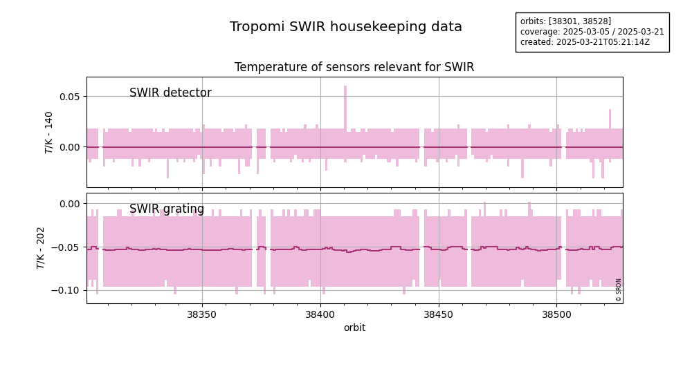
The relevant housekeeping parameters for stability of the SWIR signal and thermal background are listed in the Table below. The reports on the SWIR housekeeping parameters are generated once per day from the TROPOMI L1B engineering products. All sensors are available at 1 Hz in the L1B engineering product, but averaged over 30 seconds for the zoom plots and averaged over a full orbit in the trend plots. The mean value is shown as a line and the range between the minimum and maximum value as a band.
| Description | Unit | Nominal | Resolution |
| SWIR detector temperature | K | 140 K | 3.84 mK |
| SWIR grating temprature | K | 202 K | 8.17 mK |
| SWIR imager temprature | K | 203 K | 81.7 mk |
| SWIR OBM temperature | K | 208 K | 81.7 mk |
| calibration unit temperature | K | 292 K | 12 mK |
| SWIR detector heater current | mA | 40 mA | 0.01333 mA |
| SWIR OBM heater duty cycle | % | 55 % | 0.0256 % |
| SWIR FEE heater duty cycle | % | 50 % | 0.0256 % |
| SWIR OBM heater current | A | 0.4 A | 1.5 mA |
| SWIR FEE box heater current | A | 0.2 A | 1.5 mA |
| SWIR FEE inner frame temperature | K | 290 K | 5.3 mK |
| SWIR FEE board temperature | K | 293 K | 4.8 mK |
| SWIR FEE reference-voltage temperature | K | 294 K | 4.8 mK |
| SWIR FEE video amplifier temperature | K | 293.5 K | 4.8 mK |
| SWIR FEE video ADC temperature | K | 296.5 K | 4.8 mK |
The offset is the raw signal [V] in the limit of an exposure time of zero. Two versions of the offset are given, which should have negligible differences.
- Official – Nominal version, derived with ICM & L01b processor using radiance background measurements with exposure times between 210 and 540 ms.
- Beta-nominal – Development version, using the same data as nominal version.
Starting from orbit 9388 (2019-08-06 02:20:06 UTC), the exposure times of the radiance measurements have been reduced to obtain smaller ground-pixels. Therefore, the radiance background measurements are performed with exposure times between 166 and 840 ms.
The offset deviation is expressed as a percentage of the 0.21 V reference signal due to spectral radiance at 2313 nm (without atmospheric absorption), albedo 0.05, solar zenith angle 70 degrees, exposure time 0.54 s.
Until orbit 1740 (2018-02-13 00:37:44 UTC), the background measurements were performed during eclipse looking at the Earth. Afterwards all radiance background measurements are performed with the folding mirror closed. At the same time the duration of the background measurements has been reduced, and therefore the offset and dark-flux derived with the beta-algorithm are performed every 45 orbits during E2, instead of the nominal 15 orbits. The current beta-algorithm is part of release 2 of the ICM & L01b software, but applied on 15 orbits.

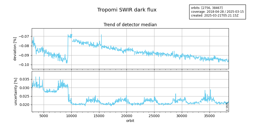
The dark flux [electron / second] is the signal rate in the absence of external light, consisting of dark current originating in the detector and thermal background current originating from the rest of the instrument. Two versions of the dark flux are given, which should have negligible differences.
- Official – Nominal version, derived with ICM & L01b processor using radiance background measurements with exposure times between 210 and 540 ms.
- Beta-nominal – Development version, using the same data as nominal version.
Starting from orbit 9388 (2019-08-06 02:20:06 UTC), the exposure times of the radiance measurements have been reduced to obtain smaller ground-pixels. Therefore, the radiance background measurements are performed with exposure times between 166 and 840 ms.
The dark-flux deviation is expressed as a percentage of the 58 ke/s reference signal current due to spectral radiance at 2313 nm (without atmospheric absorption), albedo 0.05, solar zenith angle 70 degrees.
Until orbit 1740 (2018-02-13 00:37:44 UTC), the background measurements were performed during eclipse looking at the Earth. Afterwards all radiance background measurements are performed with the folding mirror closed. At the same time the duration of the background measurements has been reduced, and therefore the offset and dark-flux derived with the beta-algorithm are performed every 45 orbits during E2, instead of the nominal 15 orbits. The current beta-algorithm is part of release 2 of the ICM & L01b software, but applied on 15 orbits.
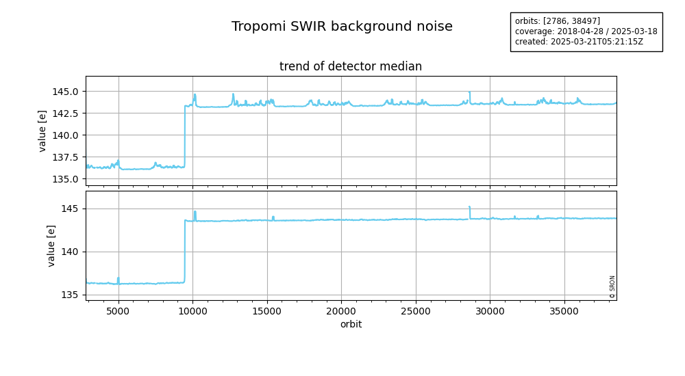
The background noise is the signal noise in the absence of external light, including read noise as well as shot noise related to the dark current and thermal background current. It is one of the tests for the detector pixel quality, determined from radiance background measurements at the longest exposure time, corrected for any averaging. The higher background noise since orbit 9388 is due to a longer exposure time.
The nominal version is corrected for any signal drift and is input for the pixel quality that is used by the L01b processor. A plain version is not drift corrected, to see whether there is a significant drift. A biweight version is also not drift corrected, but is less sensitive to deviations from a Gaussian noise distribution, for example when the dark current jumps temporarily (random telegraph signal, RTS).
The detector pixel quality indicates the expected signal quality, expressed as a value in the range 0 to 1. The dynamic pixel quality is determined from several (static and dynamic) tests. The static tests of the pixel quality algorithm were applied to on-ground measurements. The dynamic tests use in-flight dark-flux and noise data. Two versions of the pixel quality are given, which should have negligible differences.
- Official – Nominal version, pixel quality is derived using dynamic dark-flux and background noise, derived with ICM & L01b processor.
- Beta-nominal – Development version, pixel quality is derived from beta-nominal dark-flux and biweight background noise.
The quality of a pixel is indicated as:
- unusable: pixels outside the illuminated region
- worst: 0 <= value < 0.1
- bad: 0 <= value < 0.8
- good: value >= 0.8

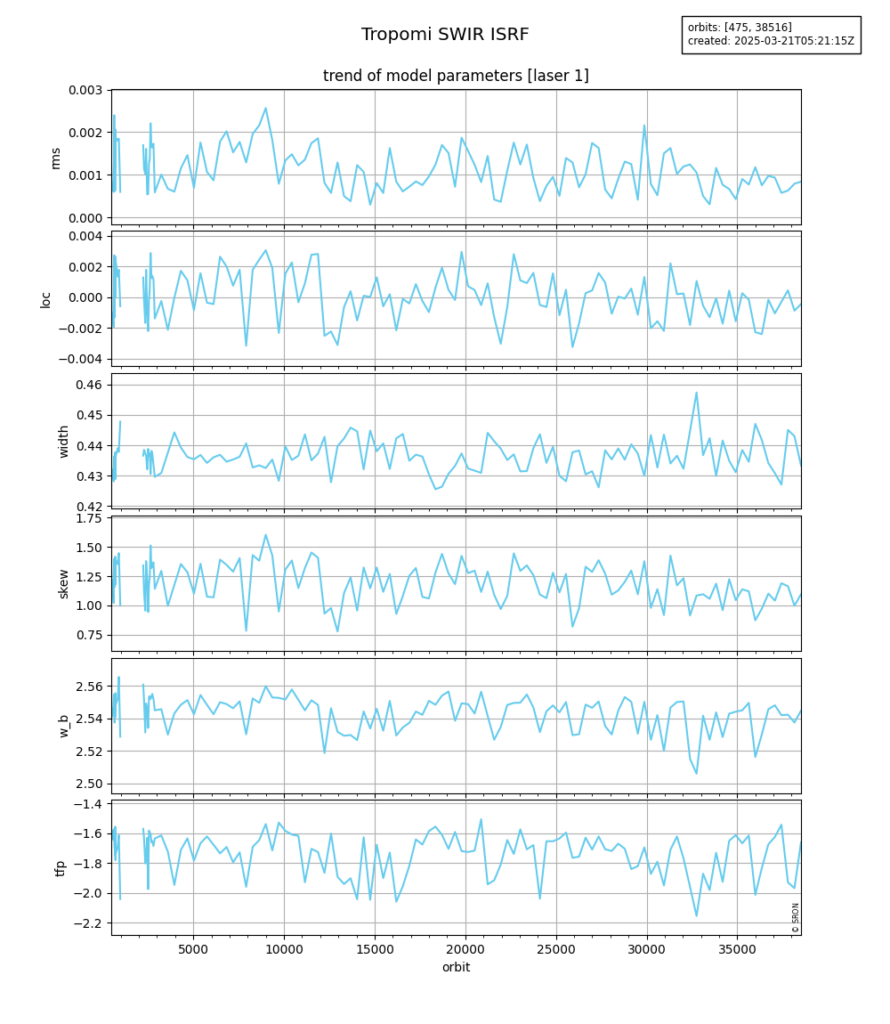
The instrument spectral response function (ISRF) of a pixel describes its signal as a function of wavelength of the incoming light. The measurements to derive a monitoring ISRF are performed by spectrally scanning one of the five on-board diode lasers [vanHees2018]. Measurements are taken monthly.
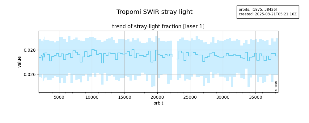
The image of a monochromatic point source forms a distribution function centred at a given detector pixel. SWIR stray light is defined as light that hits the detector more than 3 spatial or more than 4 spectral pixels from the centre. The spectral stray light is monitored using the five on-board diode lasers. The amount of stray light is expressed both as a fraction of the laser light, as well as a detector map of the laser light. Measurements are taken monthly.
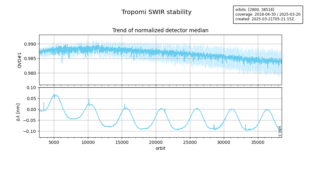
Irradiance measurements via diffusers QVD1 and QVD2, and calibration measurements with the white-light source (WLS) and the LED in the SWIR module (DLED) are used to monitor the stability of the entire instrument and the on-board light sources. All measurements are normalized by taking the ratio with reference measurements from the end of the commissioning phase, when the instrument was stable.
- swir: Ratios of normalized signals as DLED / QVD1, DLED / QVD2, DLED / WLS, WLS / QVD1, WLS / QVD2, QVD1 / QVD2, and background measurements of DLED, QVD1, QVD2, WLS.
- trend: Median of the normalized detector signals of DLED, QVD1, QVD2, WLS as a function of time.